Editing the terrain – Simple edits
Workspaces let you change the terrain model and observe the effects on the analyses. This section discusses the simple terrain editing tools. For an overview of the process please consult the introduction page.
The simple tools allow you to easily change the elevation of the
elevation for path or polygonal features. Despite their name, they are
very powerful with some types even offering complete control over
cross-section geometry.
Interpolate

This tool has two modes: Path and Area.
In Path mode, the tool interpolates linearly between the terrain elevation at the first and last point of the path.
Usage example: Cut through obstructions in the terrain, build bridges, build ramps.
In Area mode, the tool interpolates the surface between the elevations at the vertices of the polygon.
Usage example: Fill existing ditches or remove dikes.
Raise path

Interpolates linearly between the terrain elevation at the first and last point of the path, raising the path by a set height.
Features built with this tool will only raise the terrain - the tool will never decrease any elevation value. In other words, it "adds" material to the terrain, never "removes" material.
Side slopes that gently slope downwards from the new path to the existing terrain can be added, see below.
Usage example: Raise a wall that follows the terrain uphill or downhill.
Lower path

Interpolates linearly between the elevations of the first and last point of the path, lowering the path by a set height.
Features built with this tool will only lower the terrain - the tool will never increase any elevation value. In other words, it "removes" material from the terrain, never "adds" material.
Side slopes that gently slope upwards from the newly cut path to the existing terrain can be added, see below.
Usage example: Create a ditch or culvert that follows the terrain uphill or downhill.
Raise flat path or area

This tool supports a path as well as
an area mode. The path mode creates a flat path raised
by a set height over the highest elevation of any of the vertices
of the path. The area mode raises an area delineated by a
polygon relative to the highest value along the boundary of the
entire polygon.
Features built with this tool will only raise the terrain - the tool will never decrease any elevation value. In other words, it "adds" material to the terrain, never "removes" material.
Side slopes that gently slope from the newly raised path or area downwards to the existing terrain can be added, see below.
Usage example: Create a flat dam or wall. In the area mode this can be used to create building outlines.
Lower flat path or area

This tool supports a path as well as an area mode. The path mode creates a flat path, lowered by a set height relative to the minimum elevation of any of the vertices of the path. The area mode lowers an area delineated by a polygon relative to the lowest elevation value along the entire boundary of the polygon.
Features built with this tool will only lower the terrain - the tool will never increase any elevation value. In other words, it "removes" material from the terrain, never "adds" material.
Side slopes that gently slope from the newly cut path or basin upwards to the existing terrain can be added, see below.
Usage example: Create a flat culvert. In the area mode this can be used to create drainage basins.
Add to terrain

This tool supports a path as well as an area mode. Both modes increase the elevation at every cell either covered by the path or polygon by a set height.
Usage example: During a storm, inflatable barriers are used to prevent flooding. This tool can simulate the effect of such a barrier.
Subtract from terrain

This tool supports a path as well as an area mode. Both modes decreases the elevation at every cell either covered by the path or polygon by a set height.
Usage example: Dig a trench into a road (such as for piping or wiring) that follows the slope changes of the road. Deepen a canal so that the terrain reflects the bottom of the canal rather than the water surface.
A side slope extends the size of an area feature by gently sloping up or down between the feature and the existing terrain. Side slopes are often used when modeling basins.
A basin with sloped banks
You create side slopes by ticking the option create side slope in the drawing tool. The tools raise flat path or area and lower flat path or area support areas with side slopes.
You need to provide the gradient (that is, the slope or "steepness") of the side slope in the gradient field. The gradient can be specified either as an angle, in the format 45 deg or 45°, as a percentage such as 50%, or as a height difference per distance such as 2:3.
By default, side slopes will be added on the inside of the area that you have drawn. The side slopes extend with the specified gradient until they reach the desired elevation difference.
Alternatively, you can tick the box Side slopes are outside, to create side slopes that extend outwards from the area that you have drawn. In this case, you also have to specify a limit, with limits the distance from the feature up to which the side slope will extend. This is necessary to avoid accidentally modifying other parts of the terrain.
The two modes behave a bit differently:
- When adding outside slopes, the polygon you draw is a flat horizontal polygon (since it's the bottom of your basin), so in the profile view you will see all vertices at the same elevation (and you cannot change this). How far the side slopes will go depends on the elevation of the terrain, for an uneven terrain it is not easily predictable.
- When adding inside slopes, the polygon you draw
actually has 3D coordinates (SCALGO Live automatically samples the
terrain at each vertex). This makes it possible to create a basin
whose outside aligns with the terrain along the given area boundary.
From these 3D coordinates, SCALGO Live then computes the appropriate
sloping to achieve the target depth (or height for protrusions). The
depth is always measured from the lowest boundary vertex, the height is
measured from the highest boundary vertex.
When you edit the boundary of such a basin, you may have to readjust the elevations at the vertices to make sure it again aligns with the terrain, otherwise you'll have sharp edges on the boundary.
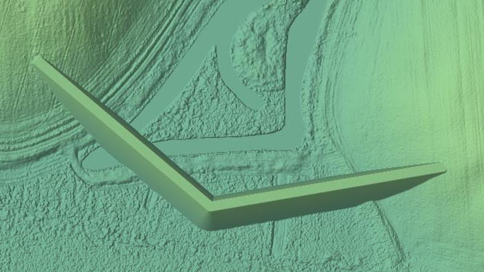
A side slope extends the size of a path feature by gently sloping up or down from the feature to the existing terrain. Side slopes are used when modeling dikes or river banks.
You create side slopes by ticking the option create side slope in the drawing tool (Raise path, lower path, raise flat path or area, lower flat path or area support side slopes).
You need to provide the gradient (that is, the slope or "steepness") of the side slope in the gradient field. The gradient can be specified either as an angle, in the format 45 deg or 45°, as a percentage such as 50%, or as a height difference per distance such as 2:3.
The limit to-field limits the distance from the feature up to which the side slope will extend. This is necessary to avoid accidentally modifying other parts of the terrain.
Using the asymmetric side slopes option, the left and right side of the feature can be given different parameters. The left and right input fields correspond to the side slopes on the left and right side of the path, as seen in the direction in which the path has been drawn.
The following diagram shows the meaning of the various attributes. A path is drawn with a width of 6m, the left gradient is 30° with a limit distance of 10m, the right gradient is 60° with a limit distance of 15m. When the limit distance is reached, the side slope is simply cut off, and a vertical wall appears.
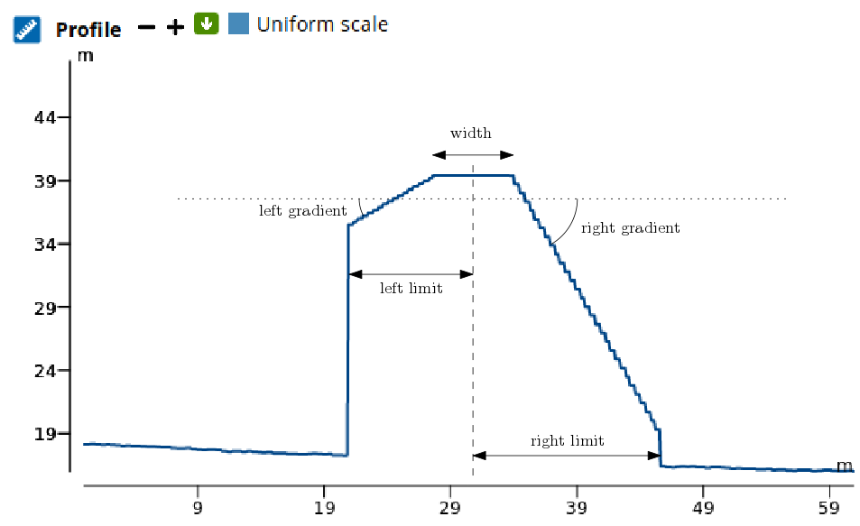
In most cases, you will want your side slopes to reach the surrounding terrain, so set your limit value larger than the expected width of the side slope. The side slope will then naturally blend into the terrain.
It is not a good idea to make the limit distance much larger, as you could see parts of your side slopes appear in unrelated parts of your terrain: a downward side slope could appear in a well or basin, an upward side slope could cut off a hill or building.
Modifying side slopes on path features
To add side slopes to a path feature that was created without them, select the feature and click edit cross section in the path info dialog (or select Edit cross section from the feature's context menu). The profile tool will appear, showing the (trivial) cross section of the path. Change the selector from Width only to With side slopes, and enter the parameters in the fields below. Note that (different from the parameters in the draw tool) the gradients are signed here: a positive number means that the side slope rises as you go away from the path feature, a negative number means that it drops as you move away from the path. Observe that the profile tool will display the shape of the feature's cross section that you are defining. You can drag vertices of the cross section display to update the parameters of your side slopes. Press Save to update the feature.
To modify the side slopes of a feature, use either Edit cross section or Set both cross sections from the feature's context menu.
Path features with more complicated cross-sections
Paths with width only and path with side slopes are the most basic forms of path features with cross sections. You can create path features with arbitrarily complex cross sections as follows:
Create a path feature (with or without side slopes). Select the feature, and select Edit cross section or Set both cross sections from the feature context menu. The profile tool appears. Change the selector to General cross section.
You are now free to draw the cross section of the feature. You can insert and delete vertices in the cross section using the context menu (or use the Shift and Control keys as shortcuts).
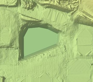
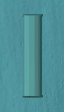
For instance, you can create a building with a nicely rounded roof:
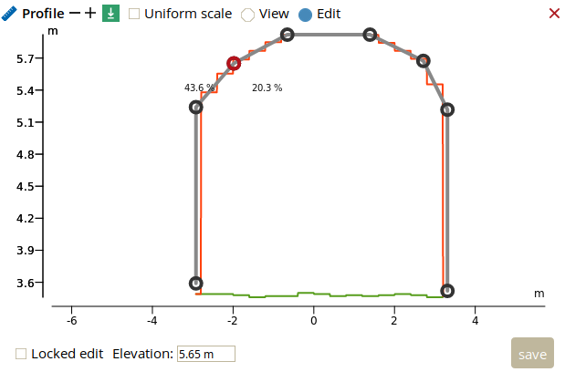
The resulting feature on the map will look like this:
Another example would be the following typical river cross section:
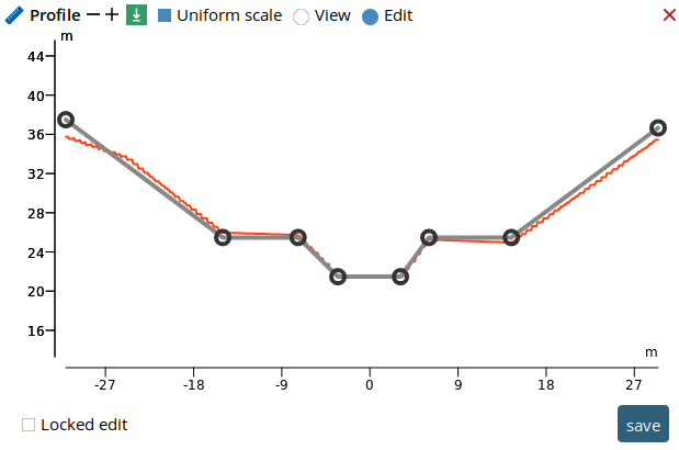
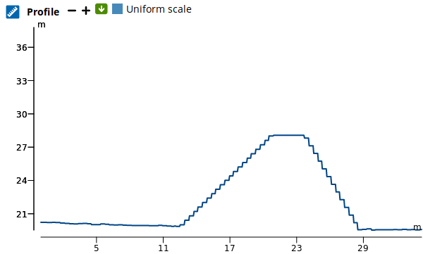
Like side slopes, cross sections are applied relative to the elevation of the path, which you can define and modify through the profile tool of the path feature.
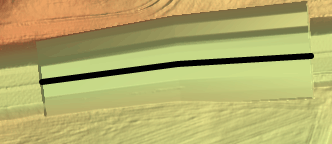
Path features with non-uniform cross sections
The cross section of a path features does not need to remain constant along the path. You can define cross sections for both ends of a path feature, and the edit will smoothly interpolate the shape of the feature between those two extremes.
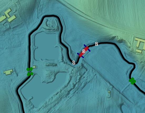
To create a path feature with distinct cross sections, first add cross sections to a path. Then select the path on the map: You will see the cross sections at the two endpoints indicated in blue on the map. You can right-click on the blue cross section, and use Edit this cross section to modify the two cross sections individually.
You can return to having the same cross section at both ends of the path by using Set both cross sections from the feature context menu.
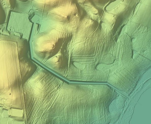
Path feature sequences
A canal whose cross section varies through different shapes along its trajectories is modeled by drawing path features for each segment. There will be a common cross section at the common endpoints of two adjacent path segments - when you edit this cross section, the shape of both adjacent path segments will change.
To build such a sequence, start by drawing one of the path segments. Use the raise path or lower path mode to draw the next segment, depending on the application. You will notice that the endpoints of the first path segment have become magnetic - when the cursor gets close to them, it will automatically snap to this endpoint. Draw consecutive path segments by letting one endpoint snap to the existing path segments. Each new segment will automatically pick up the cross section at the common endpoint. By modifying the cross section before attaching a new segment, you can let the cross section vary over the course of the long feature sequence.
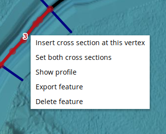
Once you have constructed a sequence of path features connected at their common endpoints, you can use Insert cross section at this vertex or Insert cross section at this position from the feature context menu to split segments into two (so that you can change the cross section in the middle). You can also use Remove this cross section on the context menu of the blue cross section to merge two consecutive path segments into one.
Once you have selected a feature using the select tool, you can right-click it to bring up the feature's context menu:
Delete feature
Deletes the feature entirely.
Export feature
Allows you to save a GeoJson representation of the edit feature.
Show profile
Brings up the profile tool so that you can edit the elevations of the vertices of the feature (see The profile tool above).
Edit cross section
This entry appears on path features that do not yet have a cross section. It allows you to create and edit a common cross section for both ends of the path feature.
Set both cross sections
This entry appears on path features that have a cross section. If the path has identical cross sections at both ends, you will be given this cross section so that you can edit it. Otherwise, a new cross section is constructed from scratch (once you save it, the existing cross sections are discarded).
Insert cross section at this vertex / at this position
This entry appears on path features that have a cross section, and allows you to split the path feature into two features that share a common endpoint with a common cross section at the specified location. The initial cross section for this location is taken from the first endpoint of the path feature.
Two operations on individual cross sections of a feature are available by right-clicking on the blue cross section (not on the feature itself):
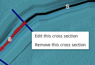
Edit this cross section
Brings up the tool to edit this cross section only.
Remove this cross section
This entry is only available when the cross section is shared by two consecutive path segments. It merges the two path segments into one.